Submit your requirements and private drawings. Please read the privacy notice first.
Function & interface review
Non-standard components
Equipment integration
SERVICE OVERVIEW
Components shaped around the equipment they serve
A mechanical component has a role within a larger system. Its mating surfaces, mounting points, motion interfaces and operating environment give the drawing its engineering context.
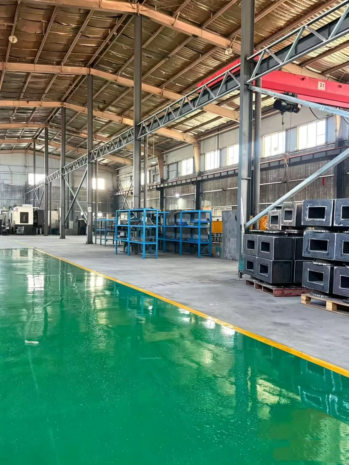
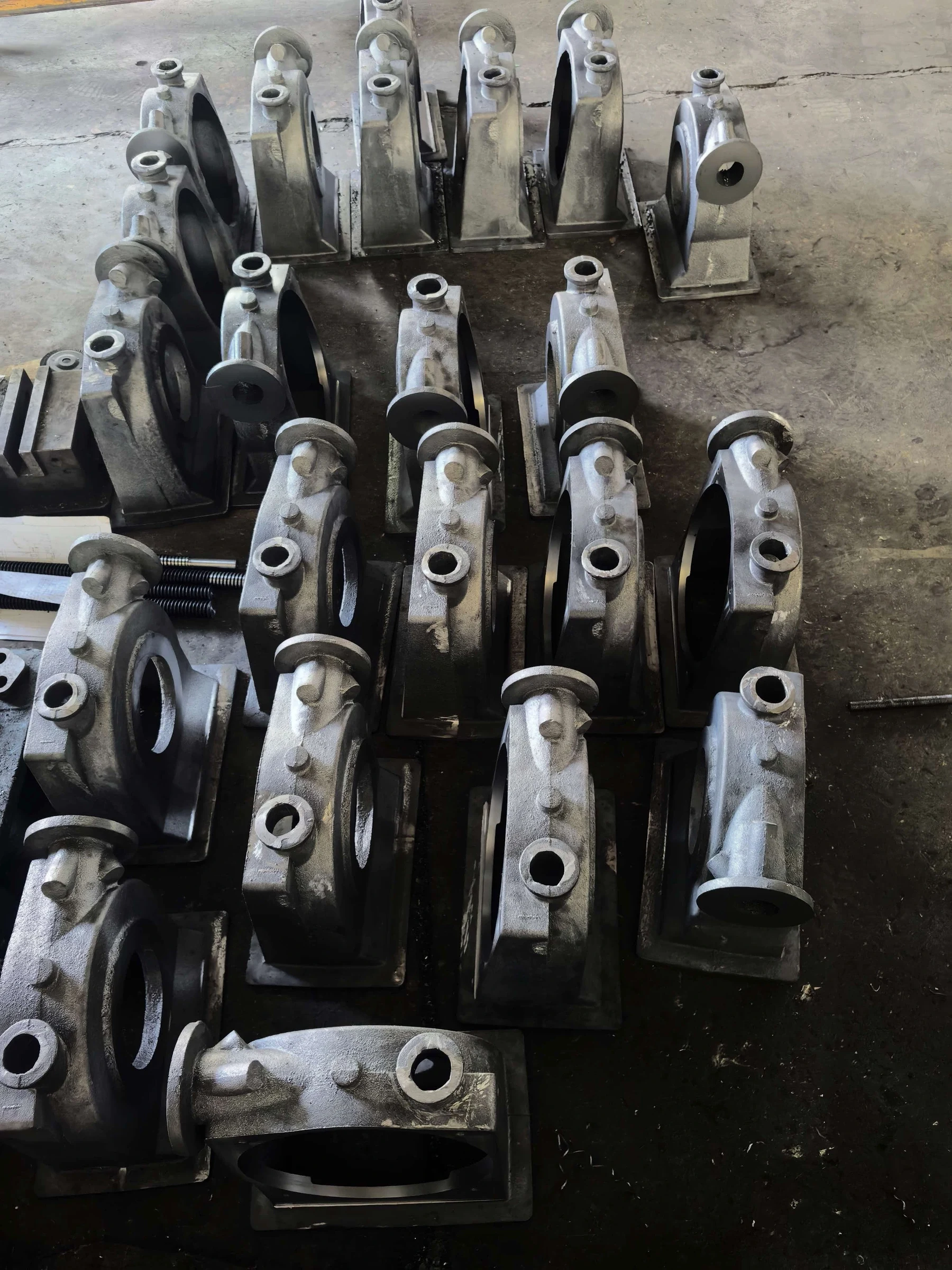
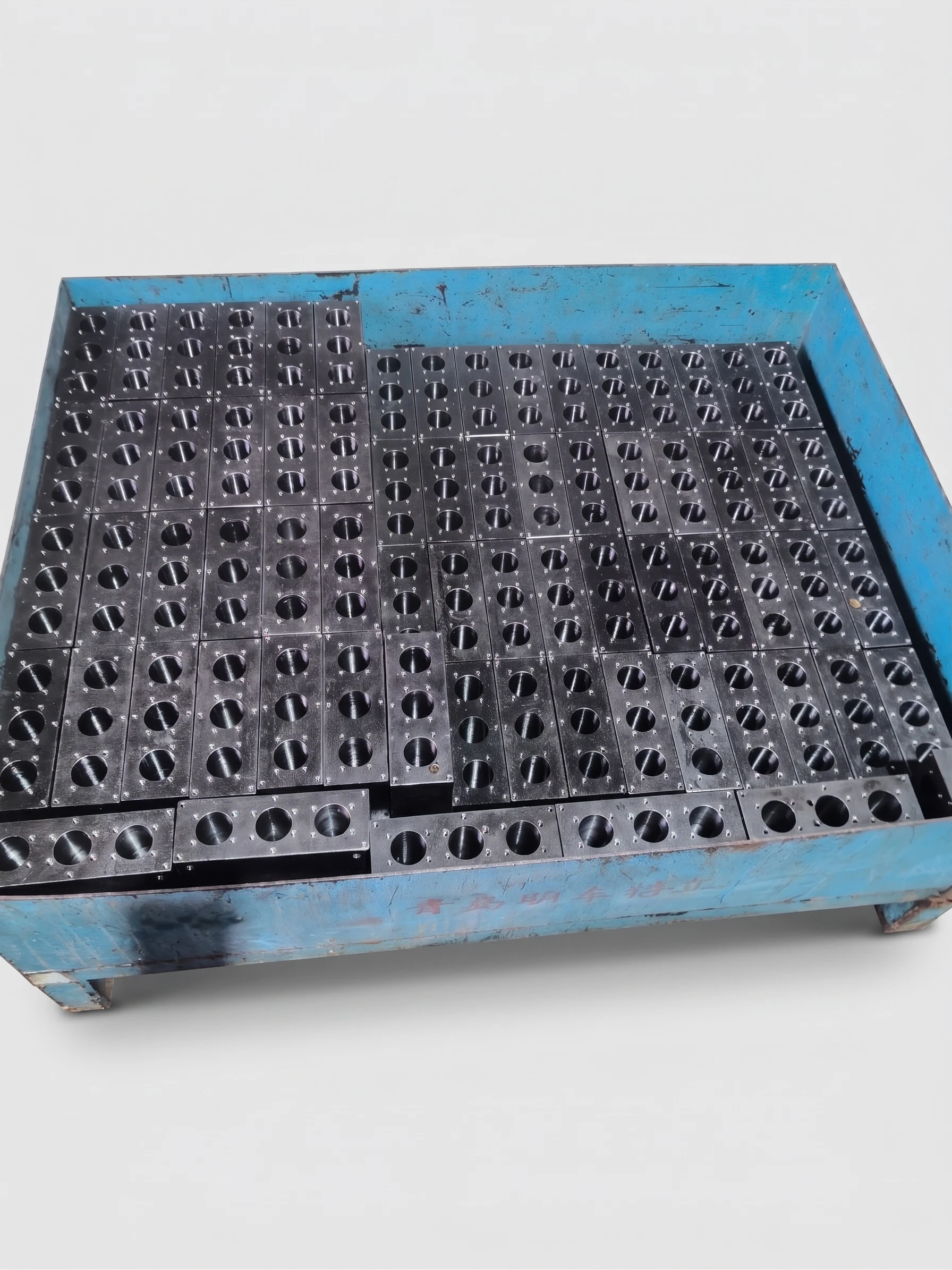
Custom parts manufacturing is not limited to one machining process. Shafts, brackets, housings and non-standard components may call for different routes. Review the function and structural fit first, then confirm materials, processes and actual factory capability for each component.
The company material range includes Q235, Q355, stainless steel 201/304, copper, aluminum, nylon and POM. This does not imply every material suits every process on this page. Batch lead time is typically 35–40 days, subject to drawings, material availability, quantity and final confirmation.
Function, loads and operating conditions
Mating parts and mounting interfaces
Drawing revisions and acceptance criteria
FACTORY PRODUCT PHOTOGRAPHS
Mechanical Parts Categories
Explore components by their role in a machine or assembly.
Conical Metal Transition Fittings
A metal transition component with a conical body and a circular mouth, showing a tapering outline and opening details. Material, the opposite interface, intended duty and forming route remain unconfirmed. The metallic finish does not establish stainless steel, sanitary suitability or a pressure rating for the component.
Metal Rods with Threaded Ends
Metal rods with long cylindrical bodies and visible external threads at both ends. The photograph supports a review of end-connection geometry, without identifying material from surface color. Thread specifications, rod length, intended use and mechanical properties require confirmation against the drawing for the requested part.
Factory product photographs show component forms; materials, dimensions and processes remain subject to confirmed drawings.
Explore related product categories
CUSTOM MANUFACTURING
Custom Manufacturing Solutions
Define the component and its interfaces before choosing the production route.
01
Build-to-Print Manufacturing
Review an approved drawing revision, critical features and the customer’s acceptance requirements.
02
OEM Mechanical Components
Clarify the component’s role, mating parts and any required identification or documentation.
03
Custom Parts Production
Plan quantities, component variants and production stages around the actual project.
04
Drawing-Based Manufacturing
Bring assembly references, fits and surface requirements into the component review.
The final route can combine machining, fabrication or other confirmed processes. Design responsibility, process availability and inspection requirements must be agreed for the project.
POTENTIAL APPLICATIONS
Typical Applications
Potential equipment contexts for custom components; each application requires its own review.
01
Industrial Machinery
Structural interfaces, housings and mechanical supports.
02
Automation Equipment
Fixtures, mounting elements and moving interfaces.
03
Electrical Equipment
Mechanical supports, enclosures and mounting parts.
04
Mechanical Assemblies
Shafts, connection parts and components with mating features.
05
Production Equipment
Custom parts shaped around equipment integration and maintenance needs.
These are potential application categories, not verified customer projects, sector approvals or completed orders.
MATERIALS & REQUIREMENTS
Material & Drawing Requirements
A complete component brief connects geometry with the intended function and assembly.
01
Technical Drawings
Provide the current drawing revision, available models and relevant assembly references.
02
Material
State the exact grade, condition and any substitution restrictions.
03
Quantity
Describe prototype, batch or scheduled release quantities without assuming a minimum order.
04
Dimensions
Identify component size, mounting locations and interfaces with mating parts.
05
Tolerance Requirements
Identify critical fits, datums and the required inspection or acceptance method.
06
Surface Treatment
Describe finish, protection, appearance and any contact-surface restrictions.
See the factory overview for the confirmed company material range. Material suitability for each process is reviewed per project. Surface treatments, standard tolerances and equipment models remain unconfirmed.
FROM DRAWING TO DELIVERY
Mechanical Parts Manufacturing Process
Start with function and interfaces, then establish a feasible manufacturing route.
01
Drawing Review
Review geometry, function and mating interfaces. Share drawings through the inquiry form using the supported file formats.
02
Process Evaluation
Select proposed routes based on structure, material and verified capability.
03
Quotation
Agree on component scope, quantity and technical requirements for pricing.
04
Manufacturing
Follow the agreed drawing revision and component production plan.
05
Inspection
Check critical features, assembly suitability and agreed records.
06
Delivery
Arrange protection, identification and delivery for the finished components.
TECHNICAL QUESTIONS
Frequently Asked Questions
Practical answers to help prepare your manufacturing brief.
01Can non-standard parts be made from our drawings?
Drawing-led custom manufacturing is the proposed service direction. Provide the approved drawing and explain the part function. The route and actual production capability must be confirmed before a manufacturing commitment.
02Is this service limited to CNC machining?
No single process defines a mechanical component. Depending on the structure, machining, sheet metal fabrication or other confirmed routes may be considered. Only verified processes should be included in the final plan.
03What if only a sample or an assembly reference is available?
A reference can help explain function, but a manufacturing project needs agreed geometry, dimensions, material and acceptance requirements. Any drawing development, measurement or design responsibility would require separate review; it is not an established service here.
04How do you review equipment compatibility?
Provide mating-part information, mounting dimensions, motion or load context and the relevant assembly drawing. Agree on critical interfaces and any required fit checks before selecting materials and processes.
05What quantity and material information is required?
State the requested quantity and production stages, exact material grade, condition and permitted alternatives. Availability, manufacturing feasibility and production planning are reviewed individually; no minimum order is assumed.
06How does the quotation process begin?
Prepare the drawing revision, function, interfaces, material, quantity, finish and inspection requirements. Submit the brief through the inquiry form and attach supported drawing files for project review. Scope, feasibility and quotation details are confirmed separately.
COMPLEMENTARY SERVICES
Explore Our Other Manufacturing Services
Different components can call for different manufacturing routes.